Table of Contents
ToggleWiring a 2 way light switch isn’t rocket science, but it does require a clear understanding of how the circuit works and which wires go where. If you’ve ever walked into a hallway or stairwell and wished you could control the same light from two different locations, you’ve needed a 2 way switch setup. This guide breaks down the wiring diagram step-by-step, walks through the installation process, and flags the common mistakes that trip up even experienced DIYers. Whether you’re retrofitting an existing switch or wiring new construction, you’ll have a working two-location light control by the time you’re done.
Key Takeaways
- A 2 way light switch wiring diagram shows how to control a single light from two separate locations using three cable runs: power source to first switch, traveler cable between switches, and cable to the light fixture.
- The common terminal on a 2 way switch connects to either the power source or light fixture, while the two traveler terminals create alternate pathways for electricity—connecting either black or red wires from the 14/3 cable.
- Safety is non-negotiable: always turn off power at the breaker panel, test with a voltage tester before touching any wires, and stop immediately if you encounter aluminum wiring, knob-and-tube, or unmarked circuits.
- The most common 2 way switch wiring mistake is confusing the common and traveler terminals; always verify terminal markings before connecting wires and ensure both switches use matching traveler wire configurations.
- Proper wire gauge (14-gauge for 15-amp circuits, 12-gauge for 20-amp) and secure wire nut connections are critical to prevent fire hazards and electrical shorts.
- Once all connections are complete and power is restored, test both switches to confirm the light toggles on and off from either location—if it fails, turn off power and methodically recheck each connection against the diagram.
What Is a 2 Way Light Switch and How Does It Work?
A 2 way light switch (also called a three-way switch in North America) allows you to control a single light fixture from two separate locations. It’s the standard setup for hallways, staircases, and large rooms with multiple entry points.
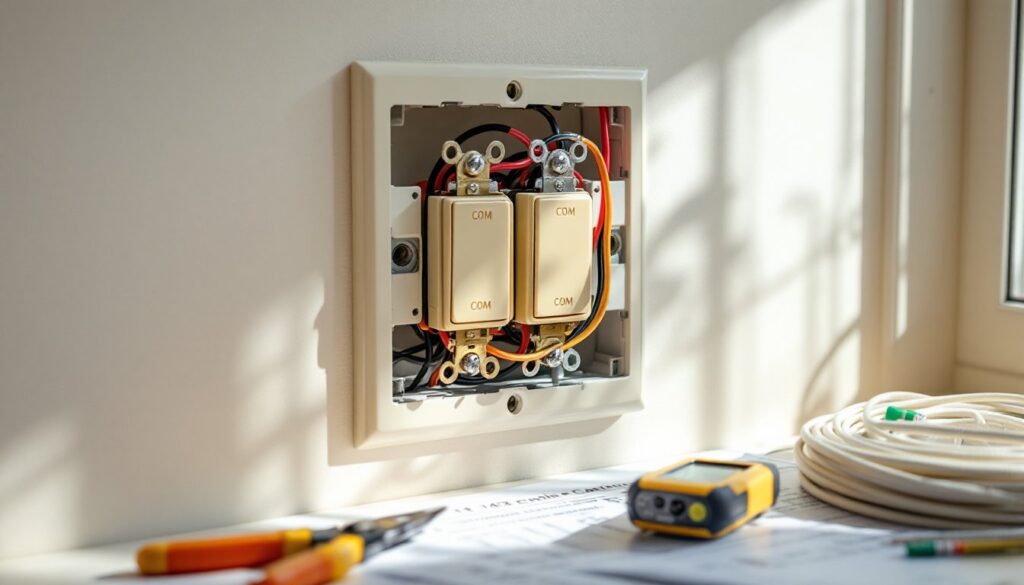
Unlike a standard single-pole switch that simply opens or closes a circuit, a 2 way switch has three terminals: one common terminal (often labeled COM or marked with a darker screw) and two traveler terminals. The common terminal connects to either the power source or the light fixture, depending on which switch you’re wiring. The two traveler terminals create alternate pathways for electricity to flow between the two switches.
Here’s how it works: when you flip either switch, it redirects the electrical path through one of the two traveler wires, completing or breaking the circuit to the light. Because both switches can independently change the state of the circuit, you can turn the light on or off from either location. The beauty of the design is that it doesn’t matter what position the other switch is in, flipping either one toggles the light.
The wiring uses 14/3 or 12/3 cable (depending on your circuit amperage) to run between the two switches. This cable contains three insulated conductors, typically black, red, and white, plus a bare copper ground. The black and red wires serve as travelers, carrying power back and forth between switches. Understanding this basic operation makes the wiring diagram much easier to follow.
Tools and Materials You’ll Need
Before you start, gather everything you’ll need. Missing a tool mid-project means a trip to the hardware store with the power shut off.
Tools:
- Voltage tester or multimeter – non-negotiable for confirming power is off
- Wire strippers – for cleanly removing insulation without nicking the conductor
- Screwdrivers (flathead and Phillips) – for terminal screws and cover plates
- Needle-nose pliers – helpful for bending wire loops and tucking wires into boxes
- Drill with bits – if you’re running new cable through studs
- Fish tape – for pulling wire through finished walls
- Flashlight or headlamp – breaker boxes and crawl spaces are rarely well-lit
Materials:
- Two 2 way (three-way) switches – verify the amperage rating matches your circuit (usually 15A)
- 14/3 NM-B cable (for 15-amp circuits) or 12/3 NM-B cable (for 20-amp circuits)
- 14/2 NM-B cable (or 12/2) for power supply and light fixture connections
- Wire nuts – assorted sizes to match wire gauge
- Electrical tape – for marking wires and securing connections
- Switch boxes – old-work boxes if retrofitting, new-work boxes for new construction
Double-check your local building code for specific requirements. Some jurisdictions require metal boxes or AFCI breakers for bedroom circuits.
Safety Precautions Before You Start
Electrical work can injure or kill you if done carelessly. Take these precautions seriously.
Turn off the power at the breaker panel. Flip the breaker for the circuit you’re working on to the OFF position. Don’t rely on the switch itself, breakers control the power.
Test before you touch. Use a non-contact voltage tester or multimeter to confirm the power is off at the switch box. Test both the switch terminals and any other wires in the box. Just because one cable is dead doesn’t mean another is.
Verify the breaker. After turning off what you think is the right breaker, flip the light switch to confirm the light doesn’t turn on. If it does, you’ve got the wrong breaker. Label your panel while you’re at it, it’ll save time on future projects.
Wear safety glasses. Wire ends are sharp, and boxes in old houses can contain debris, rust, or even rodent nests.
Work in a dry environment. Don’t wire switches with wet hands or standing on wet floors. Water and electricity don’t mix.
Know when to call a pro. If you open a box and find aluminum wiring, knob-and-tube, or a rat’s nest of unmarked wires, stop. Same if you’re uncomfortable working in the breaker panel or don’t understand the circuit layout. Hiring a licensed electrician costs less than a house fire or a trip to the ER.
Permits matter. Most jurisdictions require a permit for new wiring or circuit modifications. Replacing an existing switch on the same circuit usually doesn’t, but adding a new switch location often does. Check with your local building department. Unpermitted work can complicate insurance claims and home sales.
Step-by-Step 2 Way Light Switch Wiring Instructions
Now for the actual wiring. Take your time, double-check each connection, and don’t energize the circuit until everything is buttoned up.
Understanding the Wiring Diagram
A typical 2 way switch wiring diagram shows three cable runs:
- Power source to the first switch – a 14/2 cable carrying hot (black), neutral (white), and ground (bare copper).
- Traveler cable between the two switches – a 14/3 cable with black and red travelers, white neutral, and ground.
- Cable from the second switch to the light fixture – a 14/2 cable carrying the switched hot, neutral, and ground.
At the first switch (the one receiving power from the breaker), the incoming black hot wire connects to the common terminal. The two traveler wires (black and red from the 14/3 cable) connect to the two traveler terminals. It doesn’t matter which traveler goes to which terminal, as long as you’re consistent on both switches.
At the second switch, the outgoing black wire (headed to the light fixture) connects to the common terminal. The same two traveler wires (black and red from the 14/3 cable) connect to the traveler terminals, matching the configuration on the first switch.
All neutral wires (white) are spliced together with wire nuts in each box, they don’t connect to the switches themselves (unless you’re using smart switches that require a neutral). All ground wires are spliced together and pigtailed to the green ground screw on each switch and to the metal box if it’s metal.
Many step-by-step DIY project tutorials include visual wiring diagrams that complement written instructions, which can be helpful if you’re a visual learner.
Connecting the Wires to Each Switch
At the first switch box:
- Strip about 6 inches of outer sheathing from each cable entering the box. Strip ½ inch of insulation from each conductor.
- Identify the incoming power cable (14/2 from the breaker). The black wire is hot, this connects to the common terminal (usually a dark or brass screw, sometimes labeled COM).
- Connect the black and red wires from the 14/3 traveler cable to the two traveler terminals (usually lighter brass or silver screws). Order doesn’t matter here.
- Splice all white neutral wires together with a wire nut. If you have two cables entering the box, you’ll have two whites to join.
- Splice all bare ground wires together, including a 6-inch pigtail. Connect the pigtail to the green ground screw on the switch.
- Carefully fold the wires into the box and secure the switch with the mounting screws.
At the second switch box:
- Strip the cables as before.
- Identify the cable going to the light fixture (14/2). The black wire connects to the common terminal on this switch. This is the switched hot that will power the light.
- Connect the black and red traveler wires from the 14/3 cable to the two traveler terminals. These must match the same traveler wires from the first switch.
- Splice all white neutral wires together. This usually includes the white from the 14/3 traveler cable and the white heading to the light fixture.
- Splice all ground wires together with a pigtail to the switch ground screw.
- Tuck the wires in and mount the switch.
At the light fixture:
Connect the black (hot) wire from the switch to the black or brass terminal on the fixture. Connect the white (neutral) wire to the white or silver terminal. Connect the ground wire to the green ground screw on the fixture or box.
Many homeowners find beginner woodworking projects and electrical work share a common thread: careful measurement and attention to detail prevent most mistakes.
Once everything is connected, install the cover plates, restore power at the breaker, and test both switches. The light should turn on and off from either location. If it doesn’t, turn the power back off and recheck your connections.
Common Wiring Mistakes to Avoid
Even experienced DIYers make these errors. Knowing them ahead of time saves troubleshooting later.
Mixing up the common and traveler terminals. The most frequent mistake. The common terminal is usually a different color screw or clearly labeled. If you connect a traveler wire to the common, the circuit won’t work correctly. Double-check the switch markings before tightening screws.
Forgetting to turn off the power. It sounds obvious, but people get complacent. Always test with a voltage tester, even if you’re “sure” the breaker is off.
Using the wrong wire gauge. A 20-amp circuit requires 12-gauge wire. Using 14-gauge creates a fire hazard. Match the wire gauge to the breaker and device ratings.
Not securing wire nuts properly. A loose wire nut can arc, overheat, and start a fire. After twisting the nut on, tug each wire to confirm it’s secure. Wrap the base of the nut with electrical tape for extra insurance.
Leaving too much bare wire exposed. Only ½ inch of bare conductor should extend beyond the insulation at screw terminals. More than that risks shorts when you fold wires into the box.
Reversing hot and neutral. While the light may still work, this creates a shock hazard. The hot (black) wire should always be switched: the neutral (white) should run uninterrupted to the fixture.
Overstuffing the box. The National Electrical Code (NEC) limits the number of conductors allowed in a box based on box volume. Cramming too many wires in makes connections difficult and creates heat buildup. If your box is packed, upgrade to a larger box or use a box extender.
Skipping the ground connection. Grounding protects you from shocks if a wire comes loose and touches the metal box or switch. Always connect the ground wire, even in plastic boxes.
Not matching traveler wires. If the black traveler goes to the top terminal on the first switch, it should go to the top terminal on the second switch. Mismatched travelers prevent the circuit from working.
Testing with the cover plate off. It’s tempting, but exposed terminals and energized wires are a shock risk. Button everything up, restore power, then test.
For additional troubleshooting tips and visual guides, DIY repair tutorials offer detailed walkthroughs of common electrical fixes.
If you’ve wired everything correctly and the switches still don’t work, turn off the power and methodically check each connection against the wiring diagram. Most problems come down to a single reversed wire or loose terminal screw. Fix it right the first time, and you’ll have reliable two-location light control for decades.